New CCNA exam cover 2960 Switch. In this article I will give a you a overview of 2960 switch functionality.
2960 Overview
The 2960 series of switches comes with the LAN-based software image, which provides advanced quality of service, rate limiting, access control list (ACL), and many other features.
Depending on the series of 2960 Switch could have fast Ethernet port or dual purpose gigabit Ethernet port.
The dual-purpose Gigabit Ethernet (GE) port supports a 10/100/1000 port and an SFP (fiber) port, where one of the two ports (not both) can be used. The 2960 series supports an optional external redundant power supply (RPS) that can be attached to the rear of the chassis.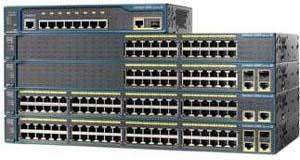
2960 LEDs and MODE Button
The front of the 2960 chassis has many LEDs that you can use to monitor the switch's activity and performance. At the top-left of the 2960's front chassis are the SYSTEM and RPS LEDs. The colors of these LEDs and their meanings are shown in Table
LED
|
Color
|
Description
|
SYSTEM
|
Green
|
The system is up and operational.
|
Amber
|
The system experienced a malfunction.
| |
Off
|
The system is powered down.
| |
RPS
|
Green
|
The RPS is attached and operational.
|
Amber
|
The RPS is installed but is not operational. Check the RPS to ensure that it hasn't failed.
| |
Flashing amber
|
Both the internal power supply and the external RPS are installed, but the RPS is providing power.
| |
Off
|
The RPS is not installed.
|
MODE Button
The meaning of the LED above each port on the front of the 2960's chassis depends on the LED's mode setting. You can change the mode by pressing the MODE button on the bottom-left side of the chassis front, below the SYSTEM and RPS LEDs. Just above the MODE button are three port-mode LEDs: STAT, DUPLX, and SPEED. By default, the STAT LED is lit, indicating that the LEDs above the Ethernet ports refer to the status of the port.
Table shows the LED colors and descriptions for the various port statuses.
Table shows the LED colors and descriptions for the various port statuses.
LED Color
|
LED Meaning
|
Green
|
A powered-up physical layer connection to the device is attached to the port.
|
Flashing green
|
Traffic is entering and/or leaving the port.
|
Flashing green and amber
|
An operational problem is occurring with the port—perhaps excessive errors or a connection problem.
|
Amber
|
The port has been disabled manually (shut down), disabled because it is in a blocking STP state, or disabled because of a security issue.
|
Off
|
No powered-up physical layer connection exists on the port.
|
If you push the MODE button once, the MODE LED will change from STAT to DUPLX. The LEDs above each of the ports will reflect the duplex setting of the associated port. If the LED above the port is off, the port is set to half-duplex; if the LED is green, the port is set to full-duplex.
By pressing the MODE button again, the MODE LED will change from DUPLX to SPEED. The 2960 supports 10/100 and 10/100/1000 ports. When the mode LED is set to SPEED, the LEDs above the port refer to the speed at which the port is operating. If the LED is off, the port is operating at 10 Mbps; if solid green, 100 Mbps; and if blinking green, 1 Gbps.
Switch Bootup Process
For your initial access to the switch, make sure you plug the rollover cable into the switch’s console port and the other end into the COM port of your computer. Start up a terminal emulation program such as HyperTerminal.
Switch have same hardware component that router have. And follow the same booting process. To know more about Cisco Devices booting process read our previous article
System Configuration Dialog
If no configuration is found, the IOS will run the setup script, commonly called the System Configuration Dialog. This script asks you questions to help it create a basic configuration on the switch. When posing questions, the setup script uses brackets ([ and ]) to indicate default values. Leaving these answers blank (that is, not supplying an answer) results in the script accepting the value indicated in brackets for the configuration component. In the script, you can configure the switch’s hostname, set up a Privilege EXEC password, assign a password for the virtual type terminals (VTYs), and set up an IP address for a VLAN interface to manage the switch remotely.
Here’s an example of this script:
Here’s an example of this script:
Would you like to enter the initial configuration dialog? [yes/no]: yes
At any point you may enter a question mark '?' for help.
Use ctrl-c to abort configuration dialog at any prompt.
Default settings are in square brackets '[]'.


0 comments:
Post a Comment